This line is similar to the Dash Thin Lines with Dots except that it has double dots within it. These conventions are fairly standard throughout the industry and are used to reduce the drawing time and space needed to convey information.

Model Train
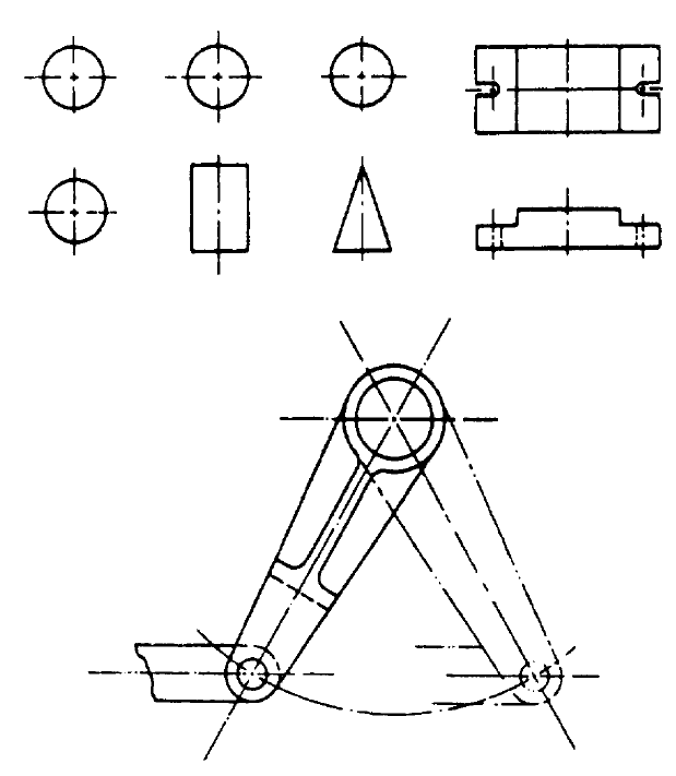
Orthographic Projection - A means of producing an accurate working drawing of a 3-dimensional object using usually three separate 2.

. A Long-Dashed Line. Drawings are composed of different line conventions because not all the lines are going. For drawings made to a large scale special conventions are used that apply to drawing breaks in such things as metal rods tubes or bars.
There is no one line that is used today that has the function of all of the. This ensures that every drawing produced within Ireland and the UK relating to a building project will follow the same standard principles. The pointed edges are in the form of an arrow.
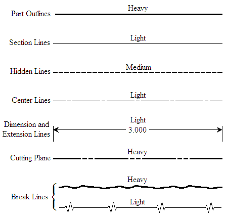
Drawing sectioning are essential means of communicating ideas. See answer 1 Best Answer Copy Line configurations and the meanings assigned to these configurations are known as line conventions. Drawings are composed of different line conventions because there are many different types of objects and each line convention is useful for accuratelyefficiently conveying information for a specific or broad range of shapesfeatures.
Drawings are composed of different line conventions in order to allow certain areas to be seen such as holes and how deep they go in. In addition contemporary arts conventions are significant. A different type of dashed line and it isnt always consistent between design firms can show things that are slightly different than a short-dashed line.
Feminist art an aim to make the audience question the social rules of society hoping to make a change to. Construction drawings communicate how something is built by showing specific assemblies and by employing architectural drawing conventions. Engineering Drawing Dimensioning for Coursework projects in Design technology.
The thickness of the lines must be chosen according to the type and size of the drawing from any of the six groups given in Table 1. The Mechanical Drawing Conventions ClipArt gallery offers 48 illustrations of the conventions used to represent different materials in mechanical drawing. In learning drafting we will approach it from the perspective of manual drafting.
This method is a universal language of describing a structure to be built and are called as Drafting. Line conventions convey information as succinctly as a physical. Examples in this gallery include the symbols for cast iron wood brass copper glass and more.
Different symbols are used to show different working equipment like in wiring diagrams and drawings so it makes it easier to understand and you can show how they interact with different types of equipment the most common symbols used are health and safety symbols to show what safety equipment needs to be used in an area such as ppe. Mechanical drawings should reflect the rigid line control of a mechanically produced drawing. Explain what basic drawings conventions are used and why there needs to be different types of drawings such as isometric and orthographic first and third angle assembly.
Contemporary art is the art of today the twenty-first century. Mr Richmonds Help pages. Lines of varying style and thickness are used in specific ways to develop and communicate graphic messages about an objects geometry.
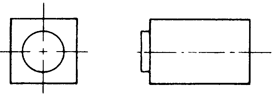
That all visible edges are shown by a line and that we assume those edges progress away from us to form faces which are normally flat and at right-angles. For wider objects a long break might have more than one pair of zigzag lines. Very lightly drawn lines to guide drawing other lines and shapes.
Alex Wheeler drawings circuit and wiring diagrams block and schematic diagrams There are several different types of drawing conventions the usual one to be used is orthographic drawings which. Why are drawings composed of different line conventions. What is an object line.
Standards and Conventions. If the drawing is made without either instruments or CAD it is called a freehand sketch. The purpose of a sectional view is to allow for a more detailed and close up view of a specific area of a part.
For general engineering drawings the types of lines recommended by the Bureau of Indian Standards shown in table 2 must be used. The change of innovations allows artist to move on from the past and allow new technology to create new styles. Every line that is used in the drawing must have.
Technical drawing relies on a number of agreed assumptions. Why are drawings composed of different line conventions. For example in Figure 5-16 a graphic symbol with an arrow drawn on a.
British Standards 308 7308. It is used for ghost outlines and bend. Arrowhead Lines are used.
That all views are of the same object and only that object but from different viewpoints and that all views are the same scale. Lines can be considered as the most expressive aspect when dealing with working drawings. The development of good detail drawings is a real engineering accomplishment and art.
Why are drawings composed of different line conventions. What is the purpose of a sectional view. They are lines with pointed edges at one or both ends.
In the construction industry all drawings are carried out to a British Standard referred to as BS 1192. In a plan view a line with long dashes is often something that is much higher above you than something that would be shown with a short-dashed line like the eaves of a roof. The next few slides show some basic line conventions and their use What is a construction line.
1 minute The structure that is planned to be built is described by using lines symbols and notes in architectural drawings. There are basically three types of drawing conventions as. At the end of dimensional lines.
Students should develop a stylized drawing technique that conforms to the rigid conventions of line drafting with added variations of artistic techniques to produce a very individualized finished. The basic drawing standards and conventions are the same regardless of what design tool you use to make the drawings.
Line Conventions Manufacturinget Org
Line Conventions Manufacturinget Org
Line Conventions Manufacturinget Org
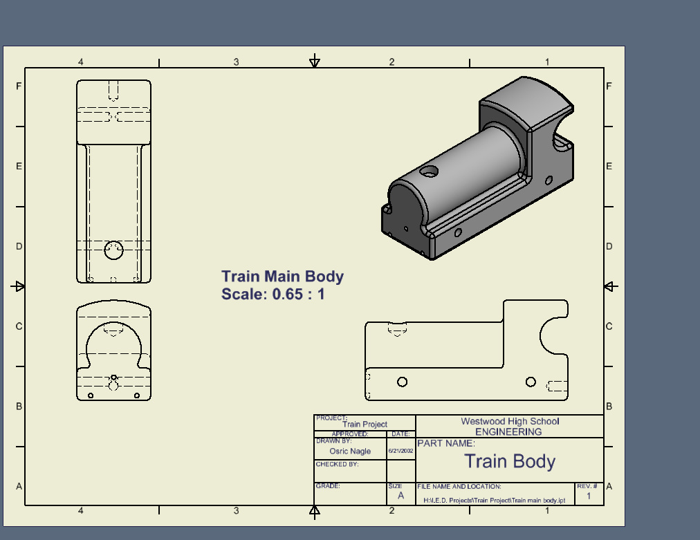
Model Train Engineering Domain
Model Train Engineering Domain

Model Train
Chase Block

Lines And Drawing Symbols Aircraft Drawings
0 comments
Post a Comment